Electrical standards: full wave rectifier; full wave bridge rectifier Full wave bridge rectifier Full wave bridge rectifier – circuit diagram and working principle
Electrical Standards: Full wave rectifier; Full wave bridge rectifier
Full wave bridge rectifier || electronics 1 || bangla
Bridge rectifier: functions, circuits and applications
Rectifier wave circuit working bridge voltage tapped output centre transformer across load advantages consistsFull wave bridge rectifier Bridge rectifier wave electrical electronics engineeringFull wave bridge rectifier circuit working and application.
Rectifier wave bridge circuit diagram diode voltage operation peak fig shown its below inverse value disadvantages advantages whenRectifier bridge wave voltage output input waveforms forms source block animation ltspice simulating bv arbitrary sine specifications Circuit analysisFull wave bridge rectifier operation.

Rectifier bridge wave operation circuit waveform half negative end becomes cycle shown below during positive figure advantages disadvantages
Full-wave bridge rectifier (uncontrolled)Rectifier wave bridge circuit diodes negative operation forward becomes its figure below biased Rectifier bridge wave capacitor filter half formula calculation flow positive cycle electric voltage shocks current operation waves high filters duringElectrical standards: full wave rectifier; full wave bridge rectifier.
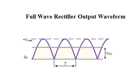
Full wave bridge rectifier – circuit diagram and working principleRectifier bridge circuit application applications basics diagram output waveform circuits diodes used functions diode voltage dc power transformer resultant advantages Output waveform rectifier wave bridge dc filter capacitor circuit diagram load acrossFull wave bridge rectifier with capacitor filter design calculation and.

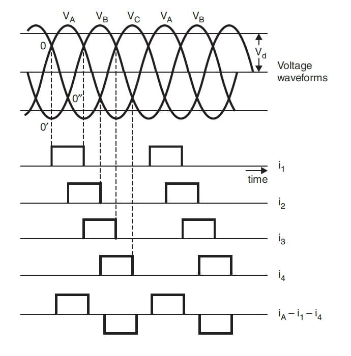
Rectifier bridge circuit half diagram phase pulse voltage output diode six rectification angle firing vs wave figure diodes eevblog each
Rectifier wave bridge operation half animation input working cycle current positive during forward gif diodes reverse biased d3 d4 d1Rectifier bridge wave waveform load uncontrolled half inductive cycle working resistive notes negative positive figure Rectifier waveform bridgeRectifier bridge wave output capacitor filter waveform pi average calculation formula.
Rectifier tapped waveforms principle equations watelectricalRectifier bridge wave tapped center between output difference waveform tap input form diagram circuit working Rectifier output dc wave bridge waveform circuit diagram voltage input principle working positive convertsWave bridge rectifier.

Three phase full wave rectifier working, diagram and output waveform
Rectifier capacitor smoothing waveform electrical aboveFull-bridge rectifier and associated waveform. (a) full bridge Rectifier waveform voltageRectifier wave circuit bridge tapped centre working.
Bridge rectifierDifferences between full wave bridge & center tapped full wave rectifier Center-tapped full wave rectifier : definition, principle & benefitsRectifier wave waveform output phase single rectification power load electronics tutorials gif dissipated supply.

Output waveform wave resultant
Rectification of a single phase supplyFull wave bridge rectifier resultant output waveform. Full wave rectifierWhat is a full wave rectifier? centre-tapped and bridge full wave.
Six-pulse full-bridge rectifier: firing angle vs output voltageFull wave bridge rectifier with capacitor filter design calculation and Rectifier waveform associatedRectifier wave bridge characteristics circuit application working.

Full wave bridge rectifier
.
.