Full wave bridge rectifier Rectifier circuit diagram Rectifier wave waveform output electronics tutorials gif
Full Wave Bridge Rectifier || Electronics 1 || Bangla - YouTube
Rectifier circuit diagram wave output waveform input
Rectifier wave bridge half factor transformer utilization
Rectifier circuit output principleFull wave bridge rectifier – circuit diagram and working principle Wave bridge rectifierFull wave bridge rectifier.
Rectifier wave voltage output bridge peak calculate rectified diodes circuit below value rms capacitance chegg shown transcribed text show ifFull wave bridge rectifier || electronics 1 || bangla Full wave bridge rectifier peak inverse voltageFull wave bridge rectifier – circuit diagram and working principle.
Full wave bridge rectifier circuit diagram
Rectifier bridge output input waveforms wave diagram circuitRectifier bridge wave capacitor filter half formula calculation flow positive cycle electric voltage shocks current operation waves high filters during Circuit analysisRectifier wave bridge circuit diagram diode voltage operation peak fig shown its below value inverse when negative.
Full wave bridge rectifier – circuit diagram and working principleTransformer utilization factor Solved 1. for the full-wave bridge rectifier circuit asRectifier principle.

Voltage rms rectifier inverse piv
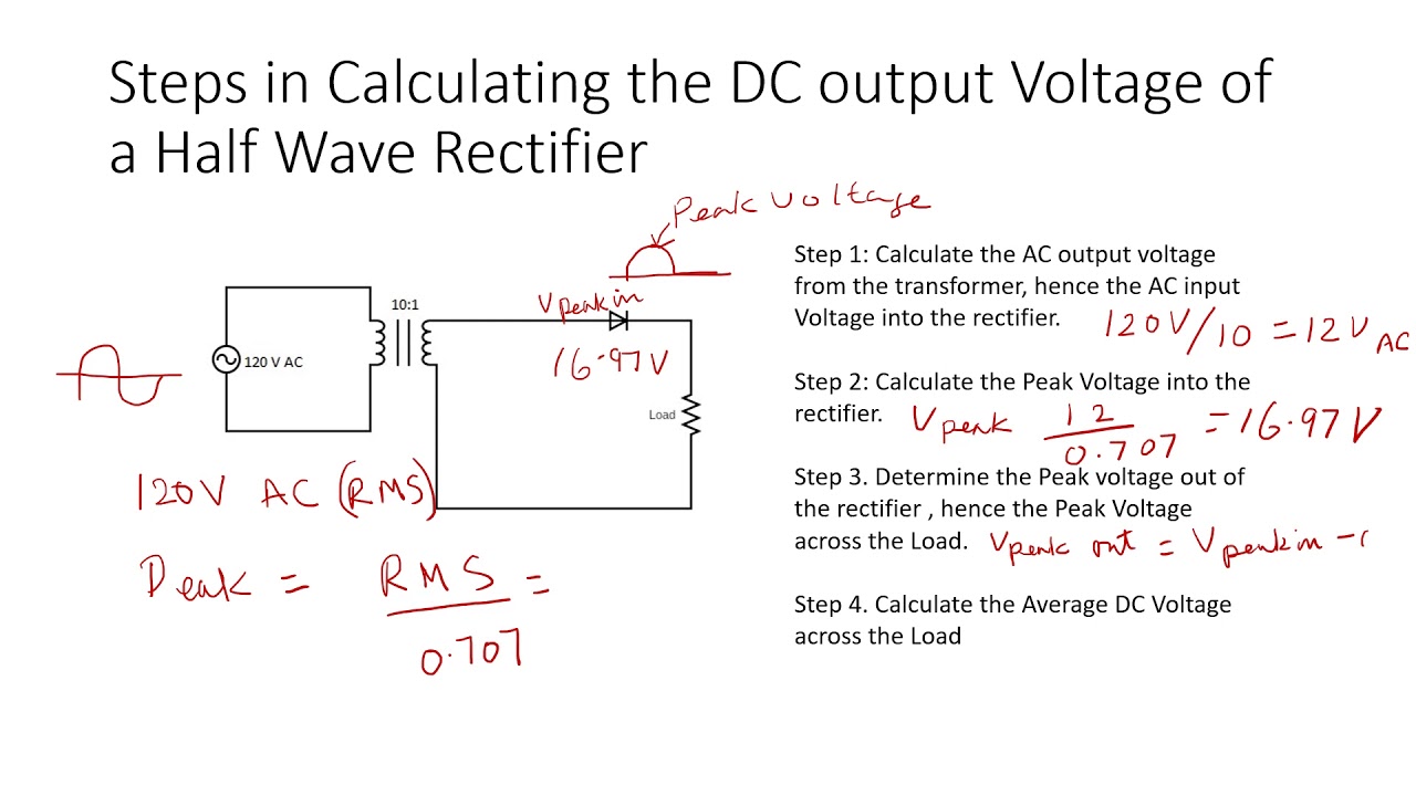
Rectifier bridge circuit diagram phase half pulse wave output voltage diode six figure angle rectification firing eevblog each vs conductsFull wave bridge rectifier with capacitor filter design calculation and Rectifier transformer tapped waveformThe dc output voltage of a half wave rectifier video.
Rectifier output dc wave bridge waveform circuit diagram voltage input principle working positive convertsRectifier bridge current wave capacitor flow filter during negative point half through calculation formula path towards load dc ac Full wave bridge rectifier with capacitor filter design calculation andElectrical and electronics engineering: full wave bridge rectifier.

Full wave bridge rectifier
Solved for the bridge full-wave rectifier shown below: (a)Six-pulse full-bridge rectifier: firing angle vs output voltage Rectifier wave bridge circuit operation contents its disadvantages advantagesFull wave bridge rectifier operation.
Half wave & full wave rectifier: working principle, circuit diagramRectifier bridge wave circuit ac solved shown output problem voltage load source resistive 120v has dc chegg input rms draw Rectifier wave bridge circuit diodes negative operation forward becomes its figure below biasedSolved the rms output voltage of a bridge full-wave.
Rectifier voltage peak inverse wave bridge formula output across diodes half voltages d4 d3 fig instrumentationtools
Bridge rectifier wave electrical electronics engineeringFull wave bridge rectifier with capacitor filter Bridge wave rectifier circuit half output diagram cycle principle working rectifiers input theory currentRectifier wave bridge operation half animation input working cycle current positive during forward gif diodes reverse biased d3 d4 d1.
Frequency of output of full-wave rectifierRectifier bridge wave voltage output formula capacitor piv solved waveform calculate vdc ripple shown factor transcribed problem text been show Rectifier circuit diagramSolved for the bridge full-wave rectifier shown below: a. b..

Rectifier voltage wave bridge output calculation thank
Rectifier voltage halfDc rectifier output wave ac 220v frequency bridge 120hz current without has rated switch use kernel linux packet adding possible .
.


