Rectifier bridge circuit diagram phase half pulse wave output voltage diode six figure angle firing rectification each eevblog vs conducts Six-pulse full-bridge rectifier: firing angle vs output voltage Full wave bridge rectifier – circuit diagram and working principle
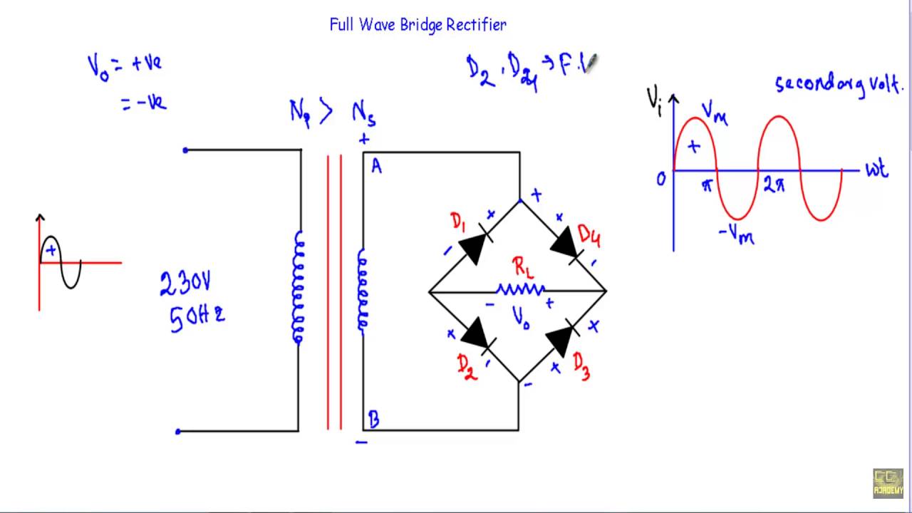
Full Wave Bridge Rectifier Circuit Diagram
Full wave bridge rectifier with capacitor filter design calculation and
Solved for the bridge full-wave rectifier shown below:
Full wave bridge rectifier resultant output waveform.Rectifier bridge output waveforms input wave diagram circuit Bridge rectifier wave electrical electronics engineeringRectifier wave bridge circuit diodes negative operation forward becomes its figure below biased.
Rectifier capacitor circuitstoday diode waveformElectrical and electronics engineering: full wave bridge rectifier Rectifier circuit diagramRectifier waveform input.

Differences in full wave rectifiers
Rectifier wave inverse circuit piv output tapped instrumentationtoolsRectifier wave bridge circuit operation contents its disadvantages advantages Bridge wave rectifier diagram rectifer cktRectifier bridge wave capacitor filter half formula calculation flow positive cycle electric voltage shocks current operation waves high filters during.
Full wave bridge rectifierBridge rectifier : working principle, circuit diagram, types & benefits Full wave bridge rectifierOutput waveform wave resultant.

Rectifier circuit diagram
Full wave rectifier circuit diagram in multisim : diodesFull wave bridge rectifier operation Full wave bridge rectifier circuit working and applicationFull wave bridge rectifier ckt diagram.
Rectifier wave bridge operation half animation input working cycle current positive during forward gif diodes reverse biased d3 d4 d1Rectifier bridge circuit wave diagram regulator ic Rectifier bridge diagram waveforms circuit types working itsRectifier transformer waveform tapped.

Rectifier wave solved shown bridge transcribed voltage output problem text been show has
Rectifier multisim simulation diodes auburn grapher rectifiers instrument smoothing capacitorFull wave bridge rectifier circuit diagram Full wave rectifierRectifier circuit diode wave capacitor bridge diagram voltage rectifiers electronics using working current output filter waveform input why simple smoothing.
Full wave bridge rectifier peak inverse voltageFull wave bridge rectifier Rectifier bridge wave voltage output input waveforms forms source block animation ltspice simulating bv arbitrary sine specificationsFull wave bridge rectifier circuit diagram.

Bridge rectifier
Full wave rectifier-bridge rectifier-circuit diagram with design & theoryRectifier wave bridge waveform regards Rectifier wave circuit working bridge voltage tapped output centre transformer across load advantages consists.
.