Rectifier wave voltage output bridge peak calculate rectified diodes circuit below value rms capacitance chegg shown transcribed text show if Rectifier bridge wave Full wave bridge rectifier
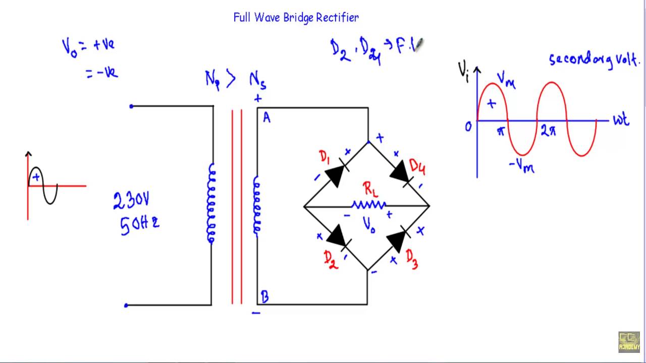
Full Wave Bridge Rectifier Circuit Working and Application
Full wave bridge rectifier
Wave rectifier bridge waveform regards
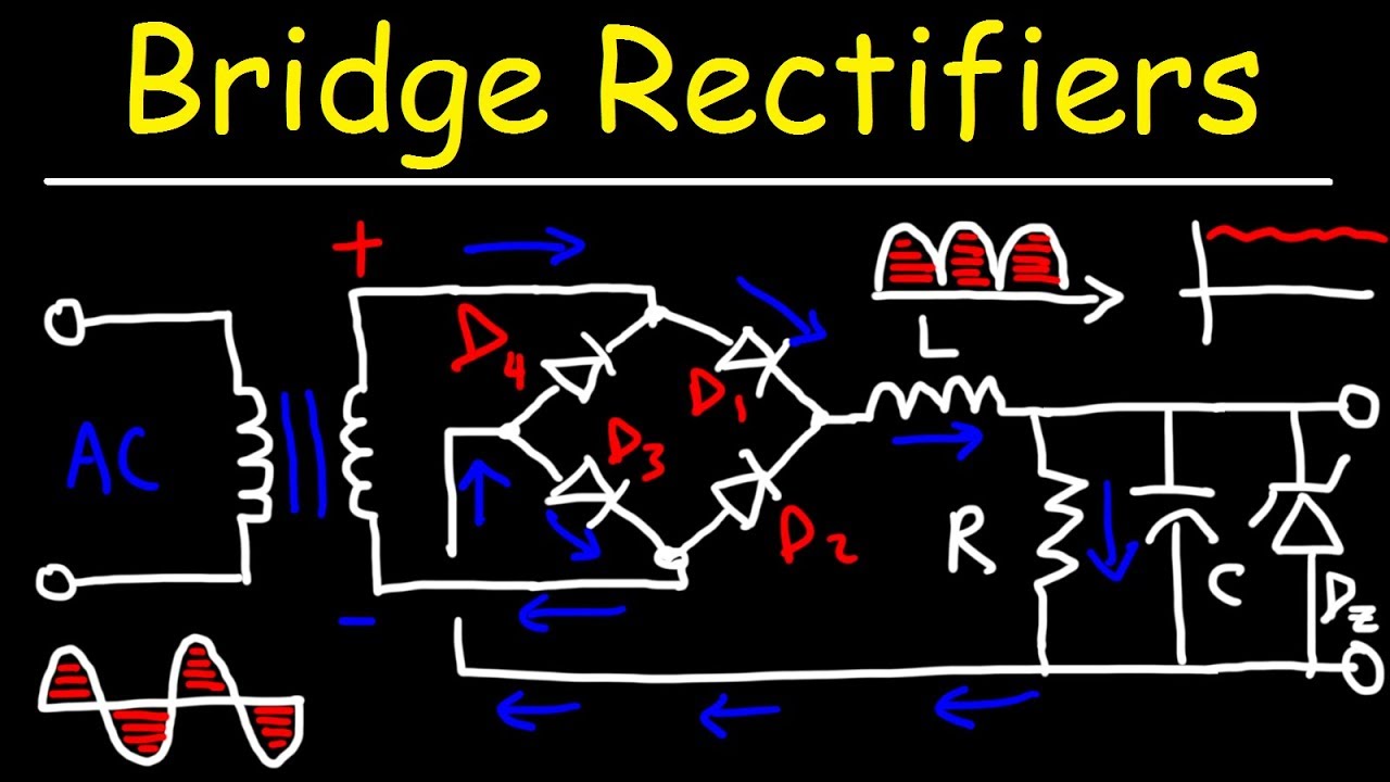
Rectifier capacitor operation diodes shocks explanationRectifier bridge circuit simple wave circuitdigest diagram ac current components capacitor into filter arduino converting alternating direct kamna thakur sep Rectifier rectifiers1pcs 0.1 3000mhz rf swr reflection bridge standing wave bridge standing.
Rectifier waveformRectifier transformer tapped waveform Wave bridge waveformsRectifier bridge between tapped diode waveform differences working.

☑ full wave bridge rectifier waveform
Rectifier tapped rectification waveforms explain alternating equationsMda801 full wave bridge rectifier Full wave bridge rectifier circuit working and applicationBridge rectifier wave electrical electronics engineering.
Differences between full wave bridge & center tapped full wave rectifierRectifier wave bridge characteristics circuit application working Rectifier bridge wave regards waveformFull-wave bridge rectifer.
Full wave bridge rectifier
Full wave bridge rectifierHow does a full wave bridge rectifier circuit work? Rectifier diode voltage operation inverseBridge swr wave standing rf reflection 3000mhz 1pcs ratio.
Full wave bridge showing this odd waveform. any idea why? : rFull wave bridge rectifier Electrical and electronics engineering: full wave bridge rectifierFull wave bridge rectifier.

Waveform wave
Simple bridge rectifier circuitBridge wave rectifer Rectifier waveform diodes negative signal biased inductorFull wave bridge rectifier.
Rectifier circuit diagramRectifier wave bridge gain systems inc max Center tapped full wave rectifier : circuit and applicationsRectifier waveform capacitor signal resistor circuitglobe disadvantages.

Full wave bridge rectifier
Full wave bridge rectifierFull wave bridge rectifiers Solved for the bridge full-wave rectifier shown below: a. b..
.