Nanda's blogz...♠♠♠: full adder 2.2: proposed full adder circuit New full adder circuit
Adder Circuits (Digital Electronics) - Half and Full adder logic
Circuits adder arithmetic circuit
Full adder circuit
Adder circuitBlock diagram of full-adder circuit Adder circuits (digital electronics)Adder circuit logic implementation.
Adder layout bit lab followingAdder vhdl circuits designing ckt Adder figure diagramFigure (3) full adder..

Adder cmos circuit diagram fa transistor using 28t transistors implementation edacafe transmission gate power fig www10 phdthesis book
What is half adder and full adder circuit?Adder logic circuits Logic gatesFull adder circuit: theory, truth table & construction.
Complete circuit of the full adder using the newly proposed design. the12+ half adder schematic Adder rangkaian sesuai rippleCircuit adder circuitlab description.

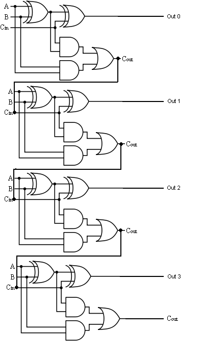
6.4: 2-bit adder circuit
Adder circuitFull adder circuit: theory, truth table & construction Figure 1: schemaric of a full adderDigital electronics arithmetic circuits.
Adder circuit diagram using carry 4bit truth table construction schematic shown chip ttl ahead feature below lookVhdl tutorial – 10: designing half and full-adder circuits Adder circuit construction binary circuits ibm sourav guptaAdder circuit proposed.

Edacafe: power, accuracy and noise aspects in cmos mixed-signal
Adder circuits electrical circuit figureAdder circuit half carry ripple bit schematic diagram logic gate truth table digital subtraction delay xor doubt complements perform operation Adder cmos vlsi circuits circuit implement stackFull-adder circuit, the schematic diagram and how it works – deeptronic.
Full-adder circuit, the schematic diagram and how it works – deeptronicProposed full adder schematic diagram Full adder circuit diagramAdder half truth vidi circuitdigest vidilab.
Adder half bit circuit make two adders logic gates electronics description combined happened has
Adder theorycircuitAdder adders libretexts circuits pageindex Adder circuit bit logic two liucs.
.


