Adder half vhdl circuit digital Adder half circuit carry ripple bit schematic diagram gate truth table delay electronics xor doubt without representation shown single below Circuit design full adder using basic gates
logic gates - Full adder 2D addressing - Electrical Engineering Stack
Adder circuit construction binary circuits ibm sourav gupta
Adder circuit gates fig boolean
Full adderAdder gates using logic circuit basic Adder circuit sum carry logic circuits electronics using boolean expression implementation combinational both tutorial two simplifiedAdder circuit (half adder, full adder and binary adder).
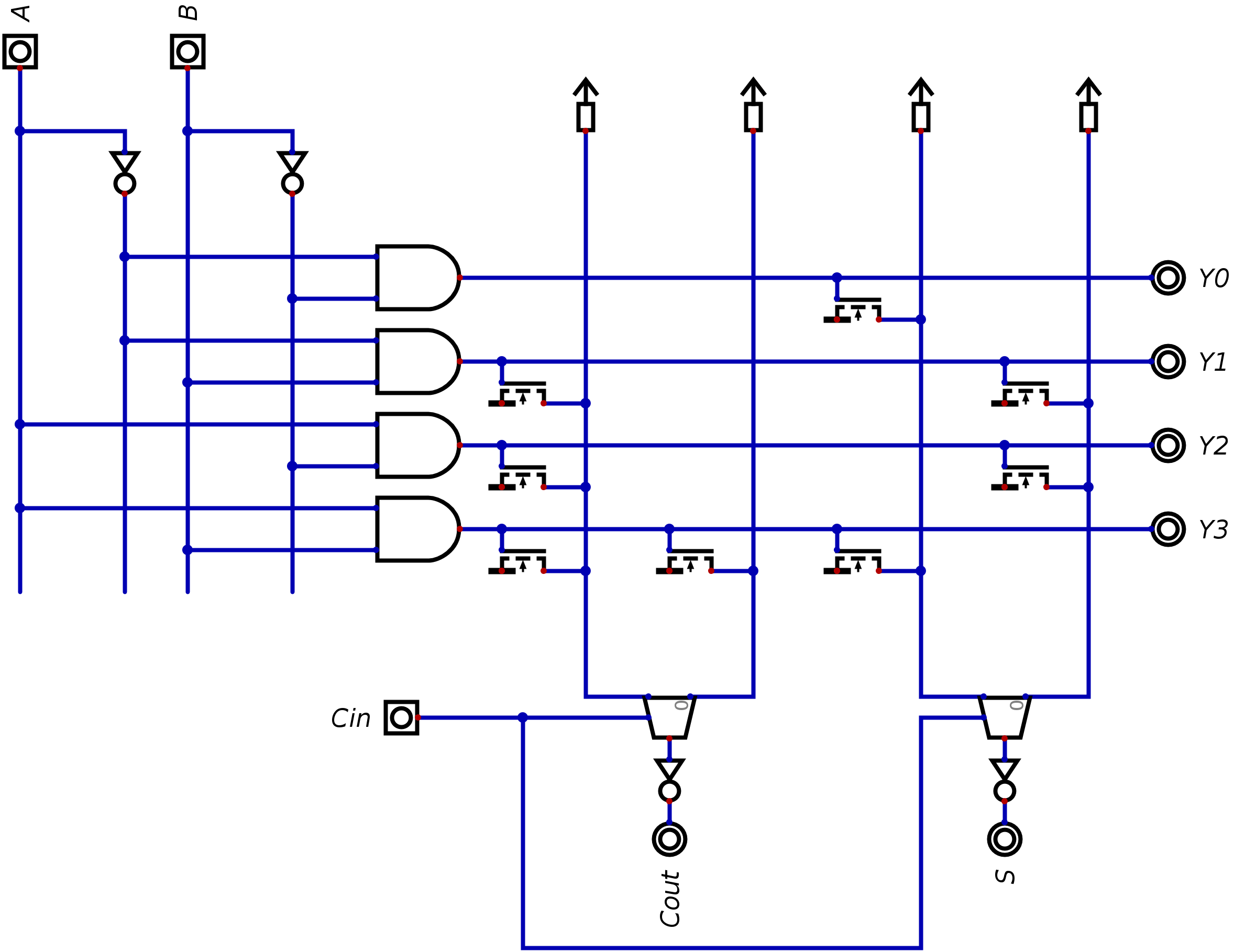
Half adder and full adder circuit-truth table,full adder using half adderFull adder circuit consisting of two and gates, one or gate, and two Full adder circuit by using basic logic gates and,or & xorVhdl half adder.
![full adder circuit by using basic logic gates AND,OR & XOR - YouTube](https://i.ytimg.com/vi/k8mRFx0BwOk/maxresdefault.jpg)
Adder addressing logic implement
Full adderAdder circuit basic Block diagram of basic full adder circuitAdder half truth logic implementation below elprocus.
Boolean algebraFull adder circuit: theory, truth table & construction Alex9ufo 聰明人求知心切: verilog 4-bit binary adder-subtractorAdder subtractor bit make carry ripple verilog binary using 4bit want two subtraction numbers addition input operation control output has.
![Full Adder : Circuit Diagram, Truth Table, Equations & Verilog Code](https://i2.wp.com/www.watelectronics.com/wp-content/uploads/Full-Addder.jpg)
Adder xor consisting
Tinkercad adderWhat is half adder and full adder circuit? Adder subtractor implementation xor logic schematic converted inverter circuits circuito logikaFull adder circuit diagram: a complete tutorial.
Adder circuit gate schematic using significance circuitlab created booleanFull adder : circuit diagram, truth table, equations & verilog code Adder nor gate logic diagram truth table using number minimum implementing required fa.
![Full Adder - Truth table & Logic Diagram | Electricalvoice](https://i2.wp.com/electricalvoice.com/wp-content/uploads/2018/05/full-adder-using-NOR-gate.png)
![Circuit design FULL ADDER USING BASIC GATES - Tinkercad](https://i2.wp.com/csg.tinkercad.com/things/fxS0eMX82eB/t725.png?rev=1603275339850000000&s=&v=1&type=circuits)
![logic gates - Full adder 2D addressing - Electrical Engineering Stack](https://i2.wp.com/i.stack.imgur.com/CMRys.png)
![Full adder circuit consisting of two And gates, one Or gate, and two](https://i2.wp.com/www.researchgate.net/profile/Martin_Sachenbacher/publication/220814552/figure/fig1/AS:645346183110658@1530873928128/Full-adder-circuit-consisting-of-two-And-gates-one-Or-gate-and-two-Xor-gates-Input-and.png)
![What is Half Adder and Full Adder Circuit? - Circuit Diagram & Truth](https://i2.wp.com/circuitglobe.com/wp-content/uploads/2015/12/HALF-ADDER-FULL-ADDER-FIG-2-compressor.jpg)
![Block Diagram of basic full adder circuit | Download Scientific Diagram](https://i2.wp.com/www.researchgate.net/profile/Shyam-Akashe/publication/260632359/figure/fig2/AS:414280903086082@1475783672448/Double-Gate-Full-Adder_Q640.jpg)
![Full Adder Circuit Diagram: A Complete Tutorial | EdrawMax](https://i2.wp.com/images.edrawsoft.com/articles/full-adder-circuit-diagram/5circuit-diagram-of-full-adder.png)
![Full Adder | Combinational logic circuits | Electronics Tutorial](https://i2.wp.com/www.electronics-tutorial.net/wp-content/uploads/2015/09/full_adder1.png)
![Full Adder Circuit: Theory, Truth Table & Construction](https://i2.wp.com/circuitdigest.com/sites/default/files/projectimage_tut/Full-Adder-Circuit.png)
![alex9ufo 聰明人求知心切: Verilog 4-bit binary Adder-Subtractor](https://i2.wp.com/media.geeksforgeeks.org/wp-content/uploads/20190824181600/dig51.png)