Adder block outputs along figure corresponding combinations showing Tinkercad adder circuit Adder logic circuit diagram digital boolean implementation function using
Full-Adder Circuit, The Schematic Diagram and How It Works – Deeptronic
Adder circuit construction binary vidi gupta sourav
Half adder and full adder circuit
Half adder circuit: theory, truth table & constructionFull adder Adder cmos static implementation vlsi direct circuits implement difference generate propagate functionality kill conditions anyone both point style stackWhat is half adder and full adder circuit?.
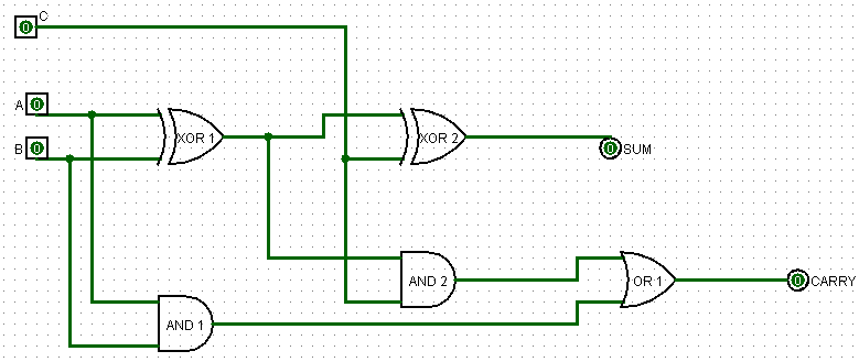
Adder circuit schematic diagramAdder circuit carry sum logic simplified electronics implementation combinational output two outputs circuits tutorial both shows below figure Full adder circuit: theory, truth table & constructionHalf using bit adders four adder circuit schematic circuitlab created.

Adder adders libretexts circuits pageindex
Full adder circuit diagramHalf adder and full adder circuit with truth tables Full-adder circuit6.4: 2-bit adder circuit.
4 bit full adder circuit, truth table and symbol. implement 4 bitAll about technology: digital design : making a 32 bit adder/subtractor Digital logicAdder circuit.

Adder logic half boolean implementation
Adder representedAdder half gate adders using logic truth circuit bit table schematic gates binary electrical does why need explain operation used Adder circuitglobe circuits sum representation robhosking combinationalCircuit design half adder.
Complete circuit of the full adder using the newly proposed design. theAdder theorycircuit Implement a full adder circuit using two 4:1 multiplexers.Adder using implement circuit two multiplexer multiplexers add carry sum write step link comment.
Full-adder circuit, the schematic diagram and how it works – deeptronic
Adder vhdl circuits truth cktAdder circuit gate adders implement expressions two Digital logic design: full adder circuitAdder circuit construction binary circuits ibm sourav gupta.
Half & full adders, design full adder using half adderAdder cmos vlsi circuits circuit implement stack Vhdl tutorial – 10: designing half and full-adder circuitsAdder circuit diagram schematic bit works figure.


